Desperation Machine 2.0
A modern vending experience
Aidan McNay, Will Barkoff
May 12th, 2023
Demonstration Video
Introduction
When you use a vending machine, the interface is usually fairly straight-forward;
you enter what you'd like, and the machine deposits it. While this is relatively
simple for the user, it doesn't leave much room for adaptability on the producer's
end. If a product suddenly becomes popular, the owner has no way to capitalize on
this increasing demand. Likewise, if a product becomes unpopular, the owner has no
way to increase the incentive for consumers to purchase it by lowering the price.
While owners could go around and manually modify the price in-person, this doesn't scale well
for large systems of machines.
To address this issue, we propose the Desperation Machine 2.0 (named due to an inside
joke resulting in the vending machines in the basement of Upson Hall being christened
the "Desperation Machine"). In addition to serving as a fully functional vending machine,
the Desperation Machine 2.0 introduces a web interface that allows an owner to monitor
their machines from a distance. This not only allows the owner to manually change prices,
but to define rules as to how the machines can automatically change their prices based on
their current stock of an item, as well as how often the item is purchased.

Project Objectives:
- Develop hardware to support vending operations
- Develop a database that allows owners to track purchases and adjust prices accordingly
- Deploy the database and web interface on the vending machine hardware
Design
Hardware
The hardware of the vending machine was constructed out of plywood, with varying thicknesses across the project (thicker for the frame, thinner for the internal components). While previous projects similar to this have used cardboard instead, we felt that plywood would make our structure more rigid and concrete, while still being easily manufacturable with the use of the table saw and laser cutter available in the adjacent lab space. Vending machines typically use rotating coils to dispense products; for these, we used coat hangers bent into a helical shape, which provided enough rigidity to move the products. These were actuated by 4 of the DC motors (controlled by 2 motor controllers) from Lab 2. These were connected to the GPIO's of our Raspberry Pi (through current-limiting resistors in series), allowing our processor to fully control the operation of the vending machine.
Software
The software of the vending machie was based around a Flask API server, which worked really well. I used the Jinja2 templating engine. The web interface consisted of several pages. The first was a login and registration page, used to sign up new users. Additionally, we had a balance page, where people could add funds to their vending machine debit accounts. We also had an item management page, which included a table of items in the vending machine, and allowed administrators to change the prices and see purchase history for each item in the machine. This allowed users to manage prices based on sale history. Finally, there was a "dispense" page, intended to be displayed on the vending machine, which allowed a user to select a product and dispense it.
To store the data for vending machine, we used a SQLite database. The database included a users table, which stored login information for each user (hashed and salted with the bcrypt algorithm), as well as account balances, stored in cents, to prevent floating point errors in currency.
Finally, to run the vending machine, we used a systemd service. This allows for complex restart rules in the event that the vending machine loses power or experiences a software failure.
Drawings
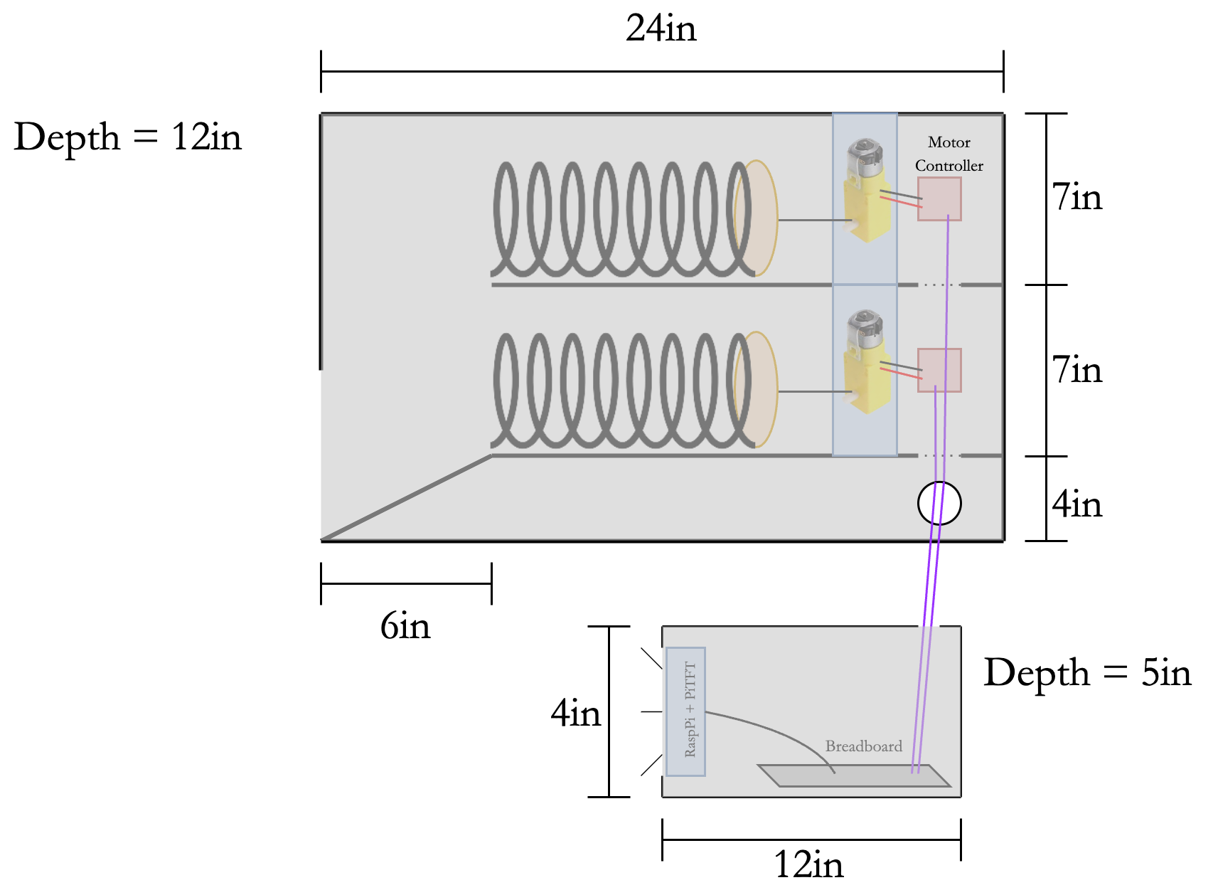
Figure 1: Overall Desperation Machine 2.0 Dimensions
One of the first tasks that was completed was the overall
dimensioning of the vending
machine. We knew the approximate size that we wanted just from general experience, but
having concrete dimensions would help a lot down the road when constructing, as we
wouldn't have to focus on design and implementation at the same time.
From measuring vending machines nearby to the lab (such as the original Desperation
Machine, as well as the vending machines on the third floor of Phillips Hall), we
determined that each channel should be at least 4 inches wide; rounding up for extra
room left us with a width of 1 foot. Additionally, each channel should be 7 inches; with
2 channels, as well as the ramp at the bottom (about 4 inches tall, to have a substantial
slope) left us with a 1.5 foot high machine. Finally, we estimated that we'd need about a
foot for the overall storage; combined with the front area for the slope (about 6 inches)
and room in the back for our electronics, we ended up with a depth of 2 feet.
Finally, we included a separate housing for our PiTFT. While this ended up not being implemented
due to time constraints, it still helped to visualize our PiTFT as separate, forcing us to define
the interface between the vending machine and processor concretely.
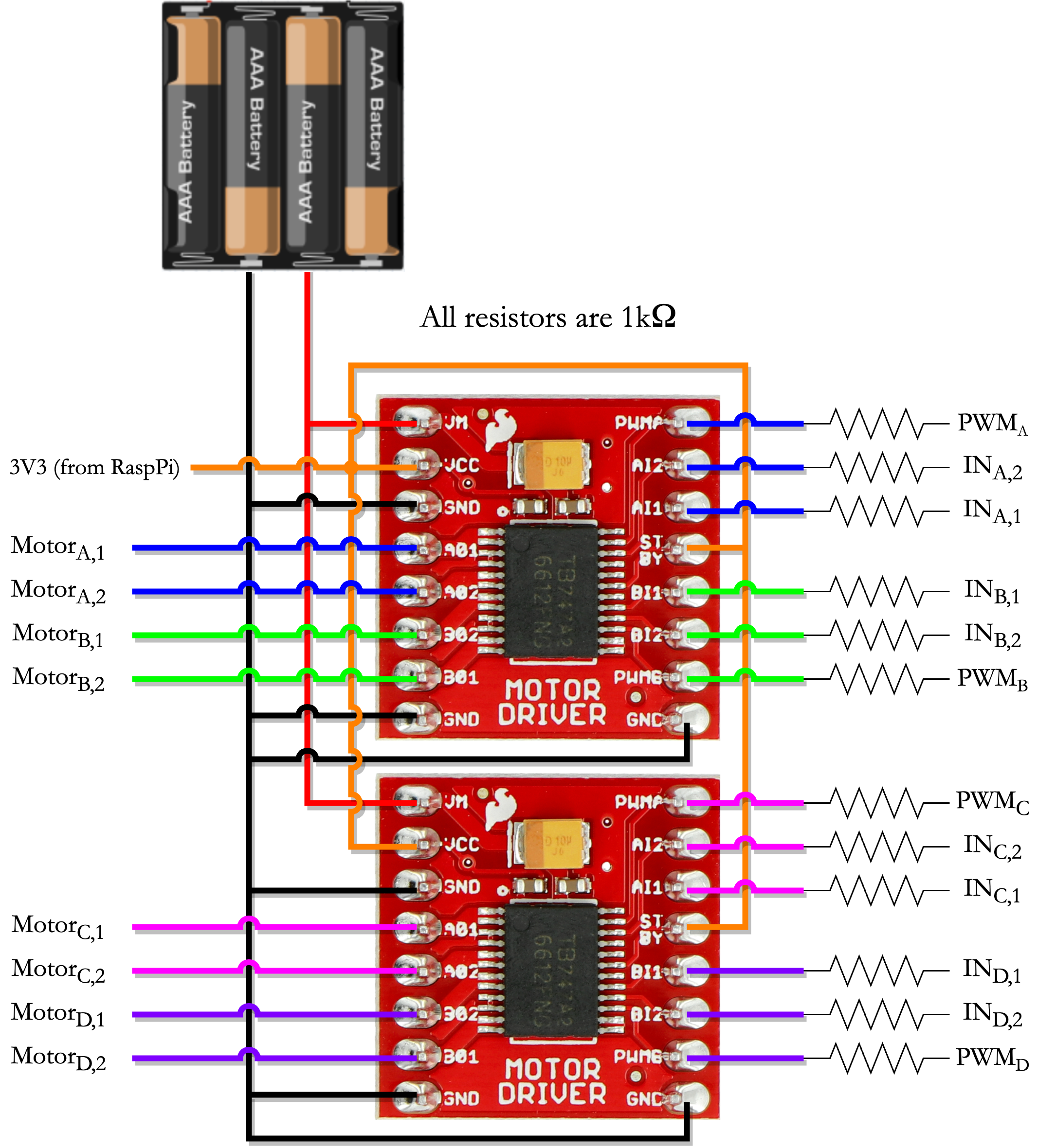
Figure 2: Schematic of the Motor Controller Board
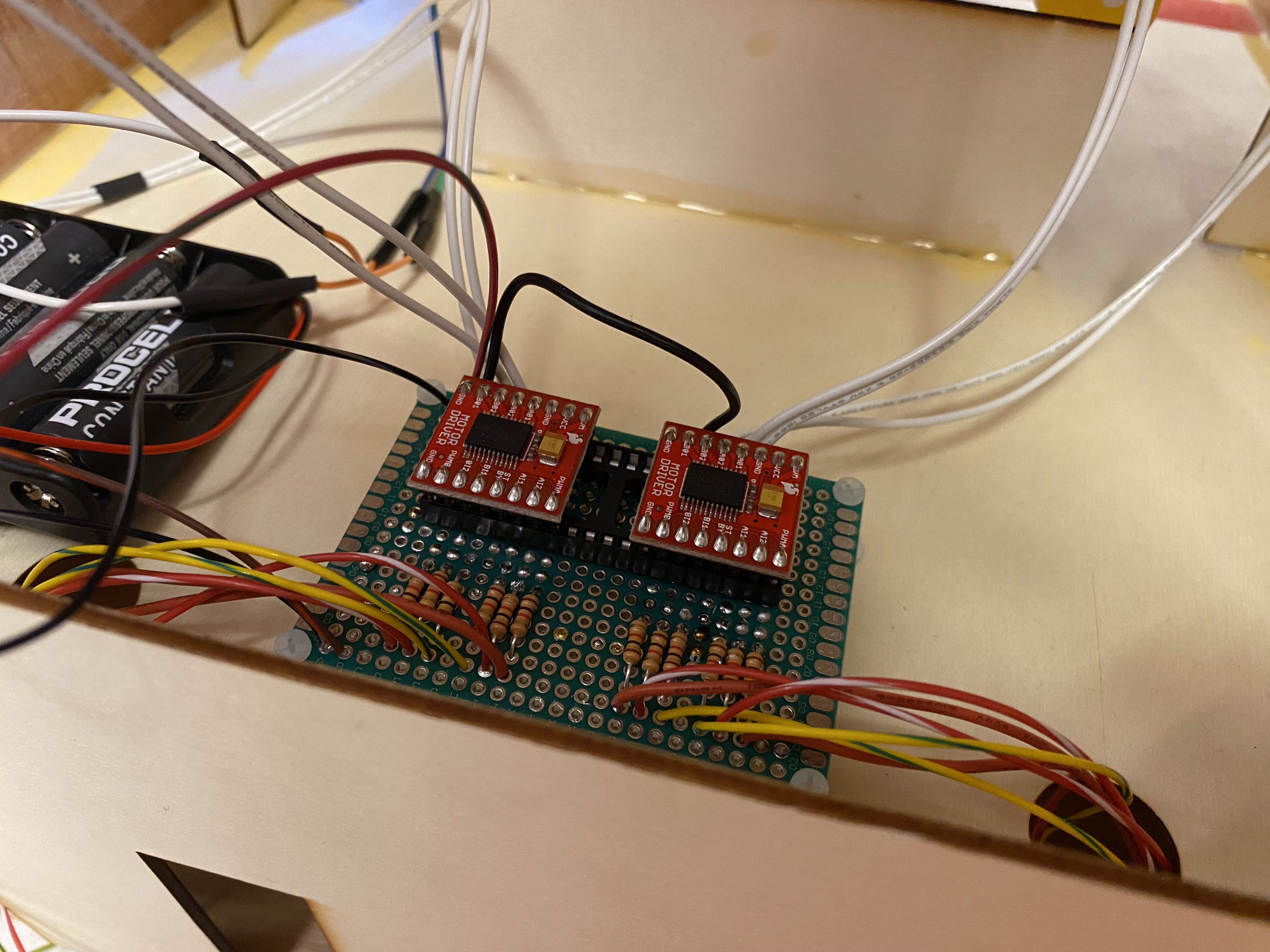
Figure 3: Completed Motor Controller Board (on a protoboard)
The other main drawing that we constructed was the schematic for our Motor Controller board, which hosts our 2 TB6612FNG Motor Controllers. This board serves as the main interface between the Raspberry Pi GPIO's and the motors that spin the vending machine coils to dispense product. Here, we connected all of the inputs from GPIO's to the needed inputs for the motor drivers (PWM signals and two binary input signals for each motor, with each motor driver being capable of controlling two motors). We then connect the analog outputs to the motors. Each of the GPIO inputs has a current-limiting resistor on it, to prevent any short-circuit current from destroying the Raspberry Pi. In terms of power, we have Vcc tied to the 3.3V coming from the Raspberry Pi, and Vm (our higher voltage for the motors) coming from the 4 AA batteries in series (generating 6V, same as the setup from Lab 3 and the one suggested by Adafruit - see References). Lastly, we tie the standby (STBY) pin high, so as to keep the motor drivers engaged (see References). By determining this schematic early, it allowed us to figure out the overall design before implementation, allowing us to only have to focus on one at a time.
Figure 3: Completed Motor Controller Board (on a protoboard)
Testing
Software
For software testing, the goal was to ensure robustness of the database and login systems, and verify that edge and corner cases were handled properly, such as in the event that a product is out of stock, or that the user has insufficient funds. In each of these cases, the user is presented with an error screen explaining the issue, and giving them an opportuity to try again.
Hardware
For our hardware testing, our goal was fairly straightforward; make sure that the coils could
output the product. To do this, we developed a Python file dispense.py
to house our code's interface to the machine. Inside this file, we defined the GPIO's for each of
the signals to the motors, and based the rest of the code off of that. This allowed us to easily
modify our wiring with little change to the code; in fact, we discovered that our initial wiring
had GPIO's that were set to default high, meaning that the motor span by default even when the code
hadn't been run. Utilizing this agile approach allowed us to quickly swap the wiring; while our current
wiring uses the debug pins (active-high on boot, meaning that the motor spins for a second when we first
turn our system on), these pins can be turned off subsequently when booting up by disabling debug, allowing
our system to be idle by default.
In dispense.py, we define a few helper functions to
initialize and cleanup our GPIO's. However, the first standalone function is motor_test.
This function tests each motor one by one, waiting for user input to progress to the next. This provided
us with a clean way to test all of our motor's functionality at once, and quickly identify and remedy
any initial issues (such as swapped wires). Once we'd verified the initial functionality, we could then
test our main application with the dispense function. This
function took in a slot location (any of tr, tl, br, bl,
corresponding to top vs. bottom and left vs. right), and dispensed a product from that location. The
actuation of motors was kept separate; while we could have re-used code by changing the pins that were
actuated when the function was called, we decided we'd rather separate the instances to have custom amounts
of time that each motor was on to dispense, allowing us to observe the motors working and correct for variation
in construction. While the dispense function was very helpful
for testing, it also provided a clean interface between the software and hardware, defining the contract
between then (similar to an ISA) through the function.
Issues
Software
I ran into two issues with the software of the project. The first was handling currency with floating point numbers. Often, I would perfom an addition or subtraction, and the result would be off by several thousanths. I fixed this problem by storing currency as an integer number of cents, so that arithmetic would be exact. The other issue that I ran into was the PiTFT display being to small to show the interface for the vending machine. We fixed this by allowing the user to perfom dispense operations on a personal device, such as their phone or personal computer. This also has the added benefit of being safer in the era of the COVID-19 pandemic.
Hardware
The first major issue with hardware was the warping of the wood. Given that plywood has different layers,
differences
in the layers, specifically when exposed to moisture, will cause the layers to expand unevenly and the wood to
warp
(hence why the wood was shipped with silica gel - to absorb any moisture). This caused issues with our overall
construction;
we couldn't rely on our sheets to be completely flat, meaning that they may not lie well with others. This led
to many struggles
getting the wood to bend how we wanted, but through the use of many clamps and interpretation of items around
the lab as
weights, we got the main components to interface well. Note that this was particularly important (and difficult)
for the overall
frame; this not only composed the main structure, but was some of the larger pieces of wood.
Another issue, although not as significant, was the GPIO's used to control the motors. When experimenting, we
realized that one
motor in particular would always start spinning on boot, and wouldn't stop until we ran our code to manually
overwrite the GPIO
value. Looking into this, we discovered that the GPIO's had different default states, given by the internal
pull-up or pull-down
resistors (see the ARM Peripherals in the References). However, we couldn't have all
GPIO's that
defaulted to low, as we didn't have enough GPIO's on the Raspberry Pi to do so. As a compromise between these,
we chose to use
the pins that are normally reserved for UART debugging (physical pins 8 and 10, GPIO's 14 and 15). While this
did mean that
the motor would be on temporarily during boot, by disabling the debugging functionality with the
sudo raspi-config command, we could make it so that the debug (and
initial value
of high) was turned off during boot, meaning that the motor only spun for a couple seconds during this period,
and remained off
even before code was run. While this might be seen as a bug, in real-life applications, our system would remain
on for long periods
of time, only turning off during service, making this bug not very impactful
Lastly, an issue that hardware found during application testing was with the strength of the motors. While our
small DC motors are
good for small applications, they lack the ability to give high torque. This lead to stalling with irregular
coils (necessitating
reshaping to become more helical - they were done by hand, leading to irregularities), but also when trying to
drive larger products,
including Welch's Fruit Snacks and CLIF bars. However, we could still have a successful functioning prototype by
switching to lighter
products that the motors could handle, including Nutri-Grain bars, granola bars, chips, pretzels, and graham
crackers. Given that
this system is only meant to be a prototype, and that it can still demonstrate functionality, this issue isn't
huge; however, a final
version would need to have stronger motors (or mechanical assist through gearing ratios) to be able to dispense
a wide range of
products.
Result
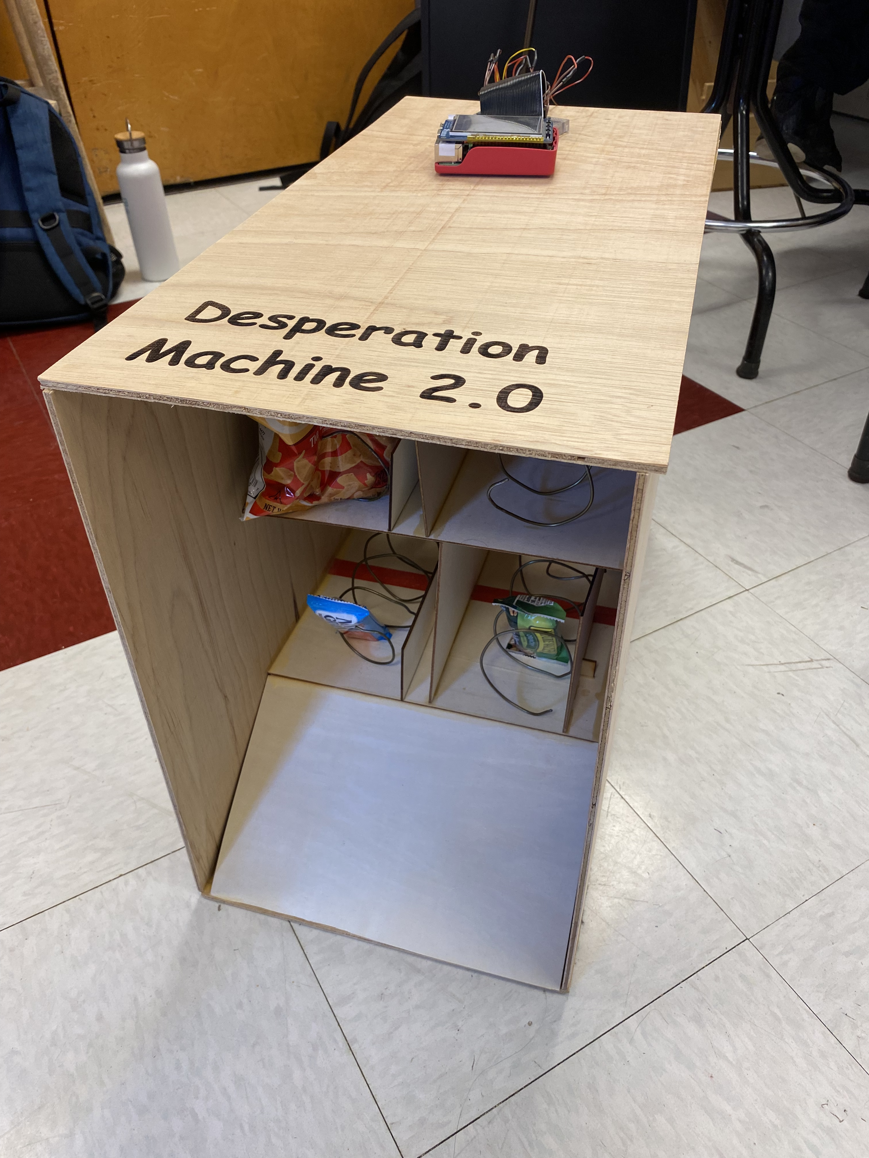
Overall View of the Vending Machine
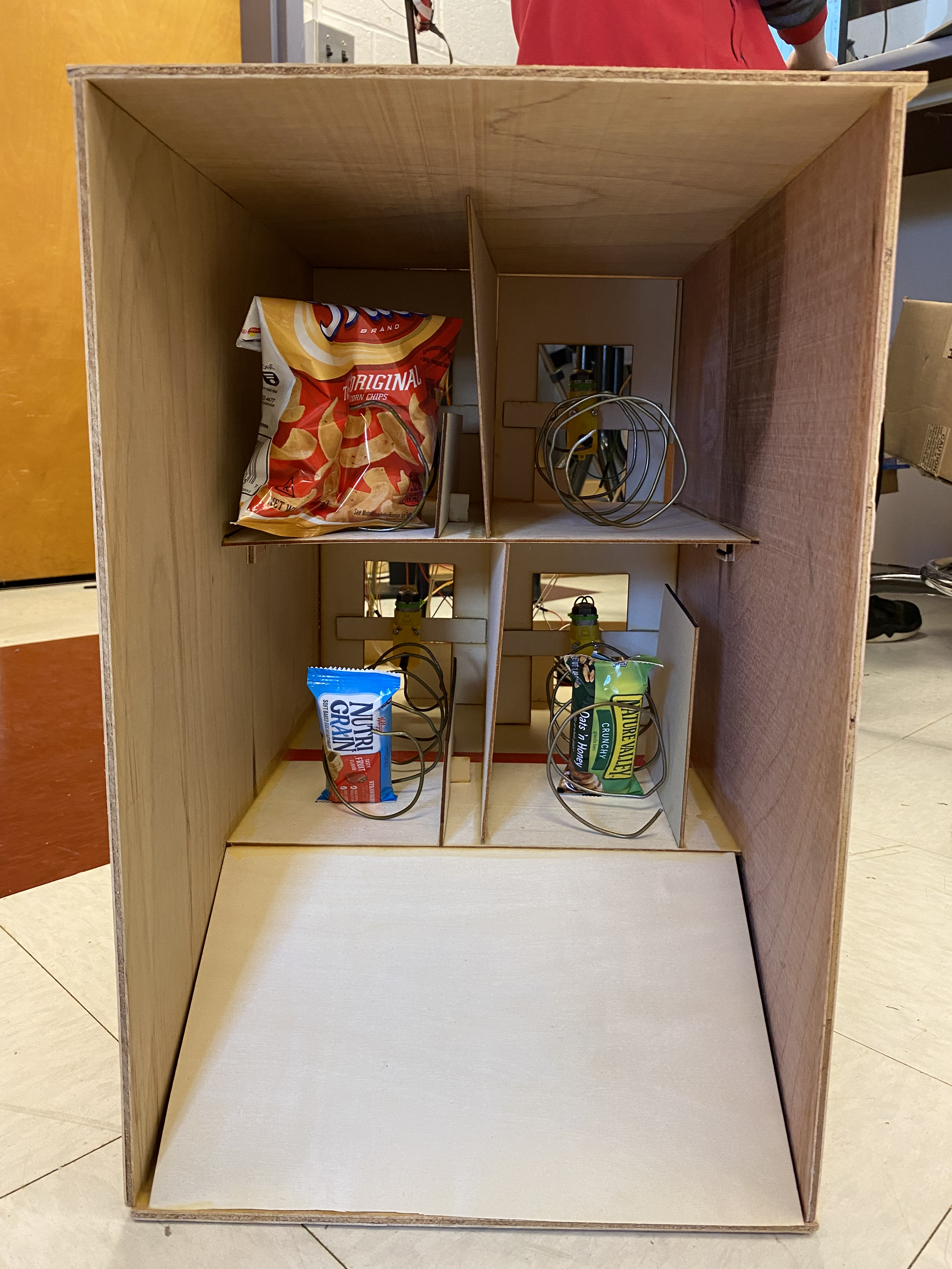
Inside View of the Vending Machine
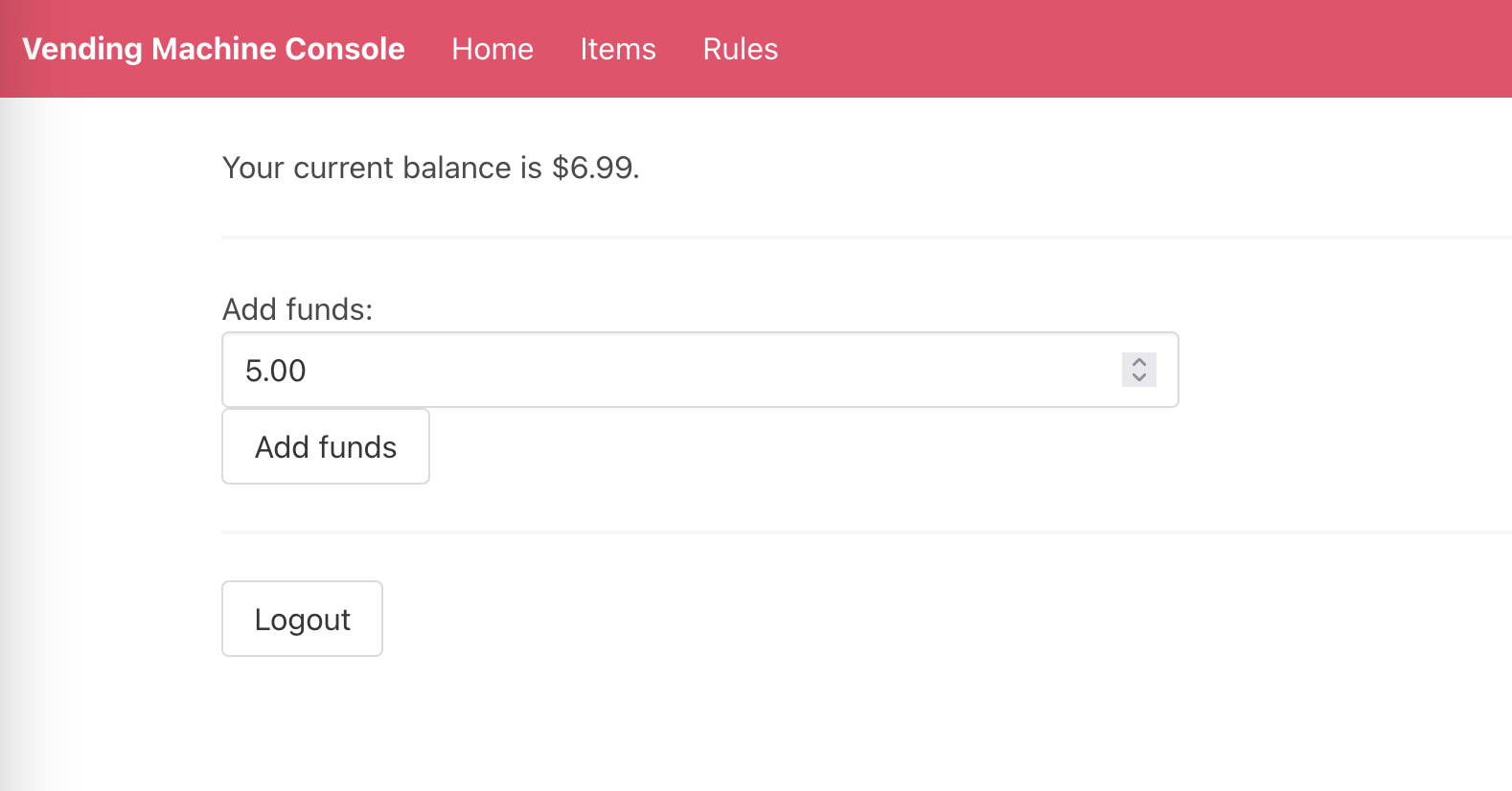
Add funds page
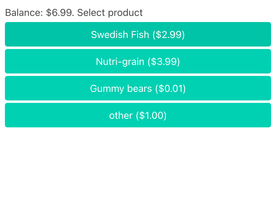
Dispense control panel
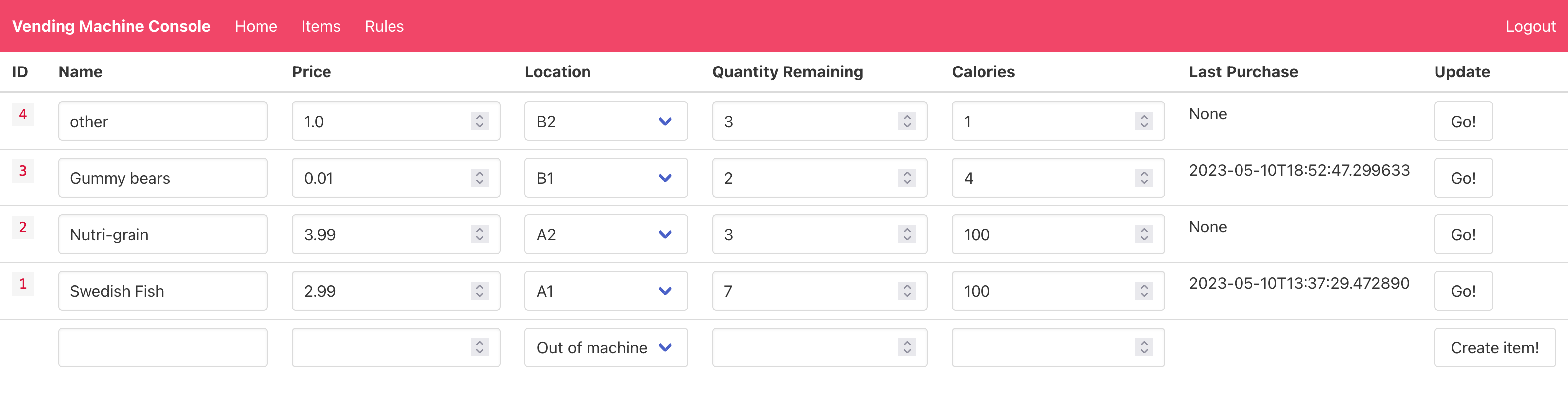
Item management page
Overall, our product turned out really well! While we weren't able to implement everything our project initially set out to do (such as have separate housing for the Raspberry Pi, or have self-updating rules), our proof-of-concept had enough detail and functionality to still be a large success. Further projects may look to expand by implementing the things that we didn't, or by exploring ways to increase the motor drive capability (such as through a driving mechanism with a high gear ratio) such that larger products could be vended. The nice thing is that much of our framework could be re-used for this; the Raspberry Pi connections could be fed into something else, the rule updates could be worked into the code, and the motors could be taken out (as they are screwed in and replacable) to substitute for a new mechanism. While we don't think our product is quite ready for the shelves just yet (especially given that users could currently just take the snacks from the front 😅), it certainly demonstrates that such a product is viable.
Work Distribution
Project Group Members Aidan and Will (along with their Rocketry team)


Will Barkoff
Wrote the software of the vending machine, including the web and user interfaces
Parts List
- Raspberry Pi - Included from Lab Setup
- Battery Holder, 4 AA Batteries - Included in Lab 3 Setup
- 4 DC Motors - $11.80
- 2 Motor Controllers - $27.00
- Wire Coat Hangers - $6.99 (although we only used 4)
- 3 1/4"-2'-2' Lauan Sanded Plywood Panels - $26.94
- 8-Pack 12"x12" Wood Panels - $19.99
- Resistors/Wires/Heat Shrink/Wood Glue - Provided in lab
Total: $85.73
References
RasPi GPIO WikiBCM2835 ARM Peripherals - GPIO Default States (page 102)
TB6612FNG Hookup Guide
Code Appendix
Code is available on GitHub